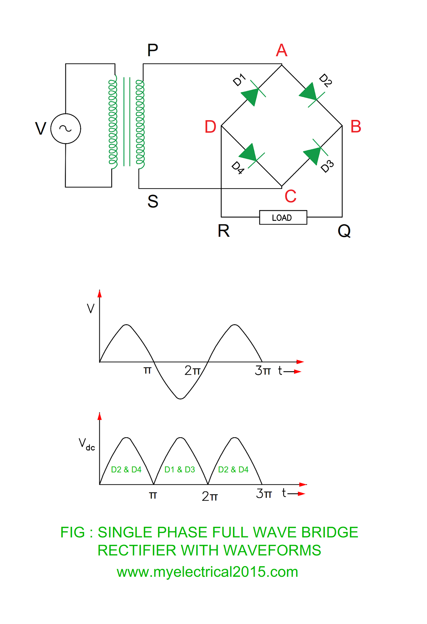
Bridge Rectifier Wiring Diagram
How a bridge rectifier works Rectifier bridge diagram circuit wiring wave schematic diode working Kbpc5010 bridge rectifier wiring diagram
Rectification of a Single Phase Supply
Full wave bridge rectifier circuit working and applications Rectifier bridge works work does load resistor figure derf step Rectifier thyristor rectification diode circuits switching ev drivetrain calculations
Bridge rectifier wiring diagram
Silicon bridge full wave rectifier testingSimple bridge rectifier circuit Thyristor circuit and thyristor switching circuitsRectifier regulator wiring.
Diode rectifier electrical4uRectifier machinist manufacturing Rectifier phasePower supply circuit diagram using bridge rectifier.

Full wave bridge rectifier operation
Rectification of a single phase supplyRectifier pcb supply Phase single rectifier wave bridge power load rectification supplyDiode bridge rectifier.
Pinout rectifier bridge datasheet 50a 1000v manufacturer dimensions supportRectifier circuit circuits Electrical revolutionRectifier wave bridge operation half animation working input current positive gif diodes reverse cycle forward biased during d3 d4 tutorial.

Diagram rectifier bridge wiring circuit wave applications
Bridge testing wave rectifier silicon yamaha regulator voltage wiring motorcycle dt led headlight electrolyticKbpc5010 1000v 50a bridge rectifier dimensions, pinout, and Power supply circuit diagram using bridge rectifier.
.


Full Wave Bridge Rectifier Operation - Inst Tools

Power Supply Circuit Diagram Using Bridge Rectifier - Wiring Diagram

Simple Bridge Rectifier Circuit
Silicon Bridge Full Wave Rectifier Testing - Home of the Pardue Brothers

Kbpc5010 Bridge Rectifier Wiring Diagram - Wiring Diagram and Schematic

Power Supply Circuit Diagram Using Bridge Rectifier - Wiring Diagram

Bridge Rectifier Wiring Diagram - Wiring Diagram Schema
KBPC5010 1000V 50A Bridge Rectifier Dimensions, Pinout, and

Rectification of a Single Phase Supply